
Computer-Controlled Machining
Once all three axes are zeroed, click on "Cut Part" to upload the file. Then, click on "Start". A pop-up box will appear requesting to switch on the spindle. To do so, turn the key provided at the side panel of the machine once.
Individual assignment:
To create a large-scale object, such as one that measures meters, the process typically involves designing, milling, and assembling various components.
Group assignment: Click here
Lab's safety training & Test runout, alignment, fixturing, speeds, feeds, materials, and toolpaths for your machine Click here
Computer-Controlled Machining
Computer numerical control (CNC) machining, a pivotal technique in modern manufacturing, harnesses computerized software and hardware to orchestrate the movements of cutting tools, thereby sculpting materials into desired products. Renowned for their versatility, CNC machines excel at accurately cutting, drilling, and milling a wide array of materials including wood, metal, plastics, and composites. The accompanying software empowers users to craft intricate designs, ensuring meticulous replication by the machine.
This assignment delves into the realm of CNC by embarking on a project aimed at creating a substantial object. Through this endeavor, our objective is to grasp the machine's capabilities and explore its boundless potential.
Design
My concept involves crafting a sled inspired by Santa Claus for the Christmas season. I've meticulously designed this sled using Fusion 360 software.
Following the design process, I translated the sled design into a flat pattern configuration.
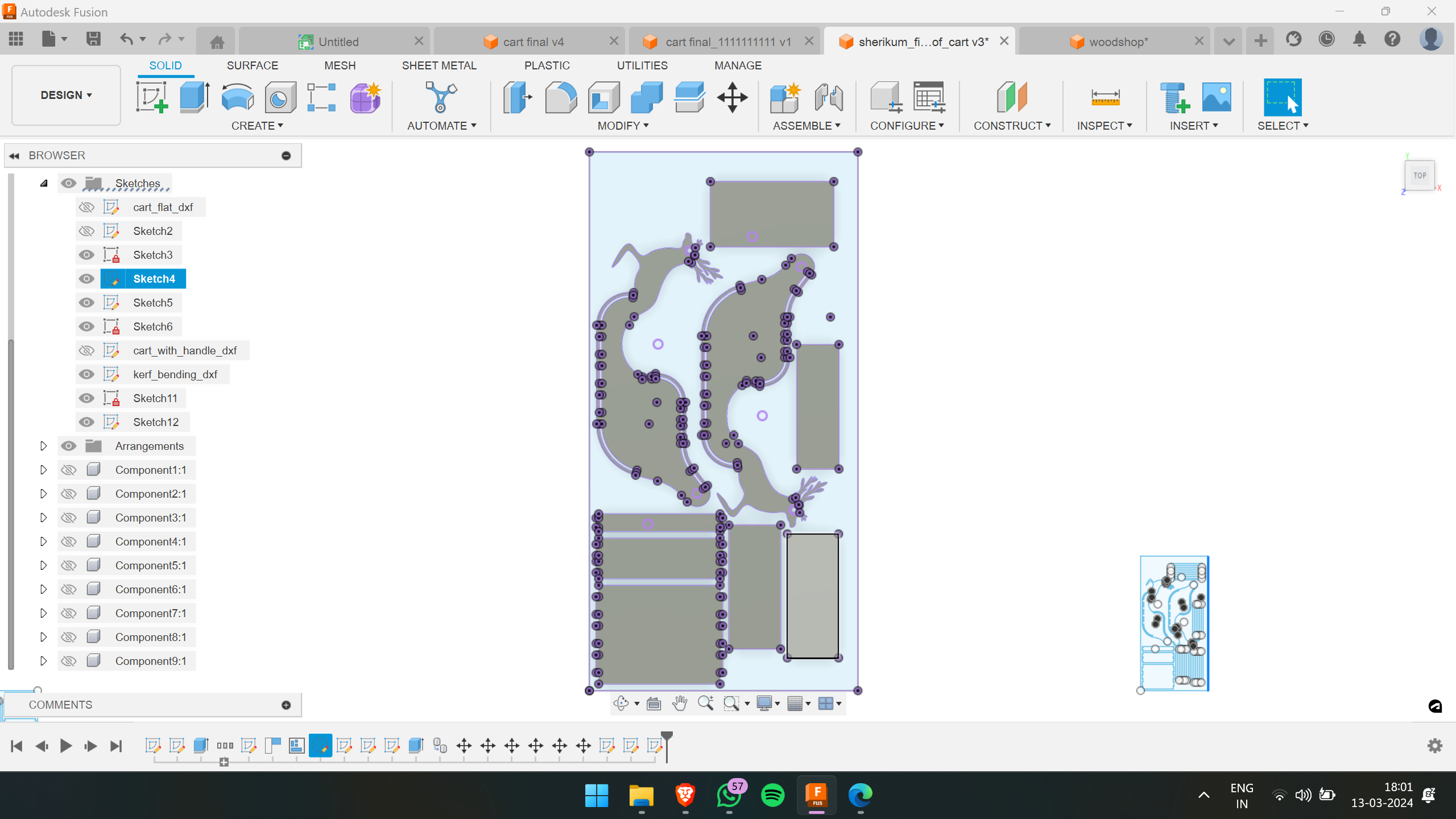
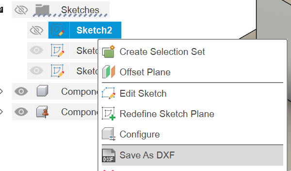
Then, I projected the sketch face and saved it as a .dxf file.
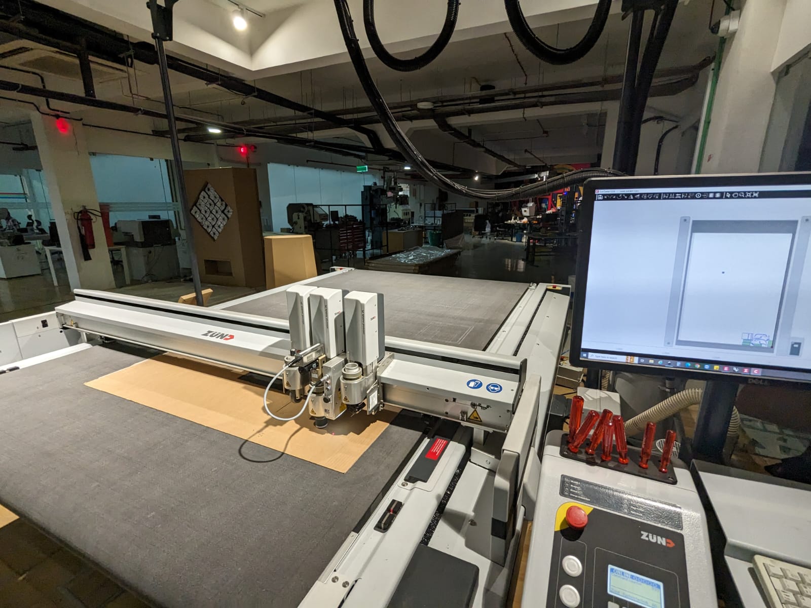
Afterwards, I scaled down the design to create a miniature version of the sled. This allowed me to visually inspect its appearance and identify any potential errors. For this purpose, I utilized 3mm cardboard and employed the Zund machine for precision cutting.
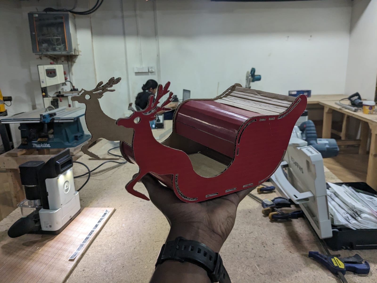
Following the cutting process, I assembled the pieces together, resulting in the completed miniature sled.
The next step involves cutting the design from plywood on a larger scale, typically in meters.
The cardboard models turned out well, so I proceeded to prepare for the CNC cutting.
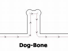
Dogbones
I provided dogbones at all the slots. Dogbones are fillets added to internal corners to ensure complete material clearance by the milling cutter. Since end mills are round, they can't create sharp internal corners. Without dogbones, parts may not fit properly due to the radius left by the tool. I used the Fusion plugin Nifty Dogbone for this purpose.
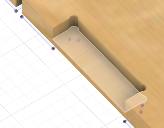
Note: I added pockets and side grooves to achieve a smooth finish on the outside. It's important to close the sketch lines at the sides if they're for pockets, and then project the pockets as a whole.
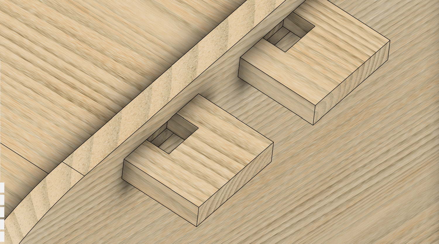
The type of joints I used is a kind of pin-slot joint. Here is a picture of the joint.
VCarve
VCarve is a CAM software for CNC milling and engraving. Instead of using Fusion for toolpath CAM as suggested by our instructor, Mufeed, we opted for VCarve. I imported my .dxf file into VCarve and set basic parameters such as job size, origin, and material thickness. Before assigning the thickness value, I measured the exact thickness of the plywood using a vernier caliper. It was clear from the measurements that the thickness varied between 11.8mm to 12.3mm. Therefore, I inputted 12mm as the thickness in the software.
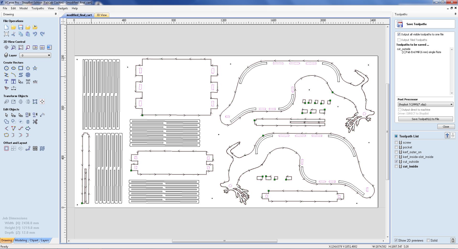
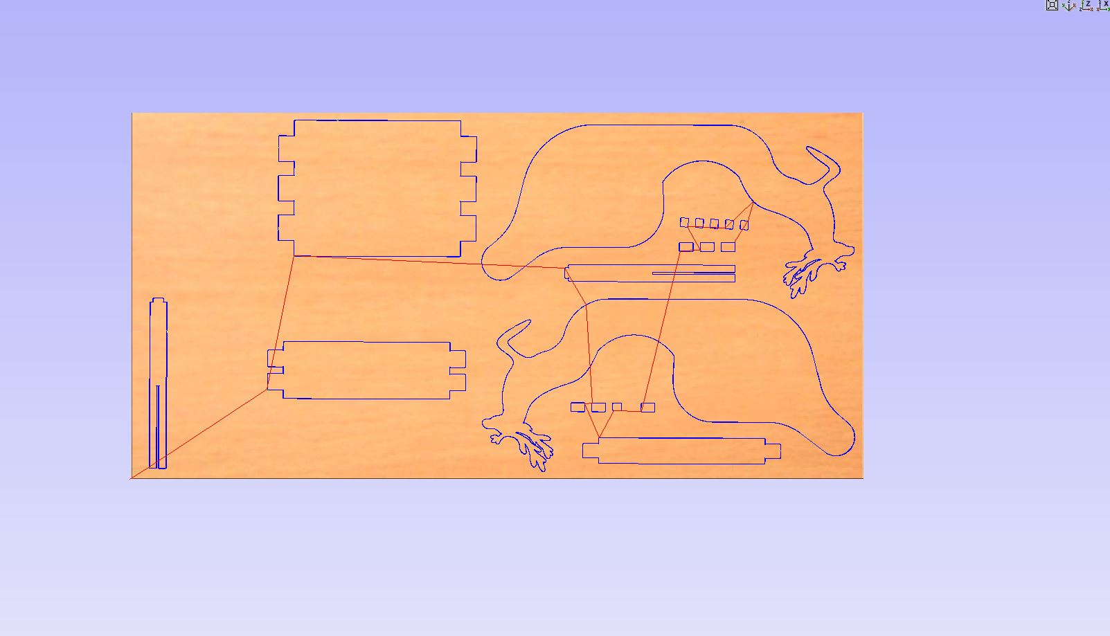
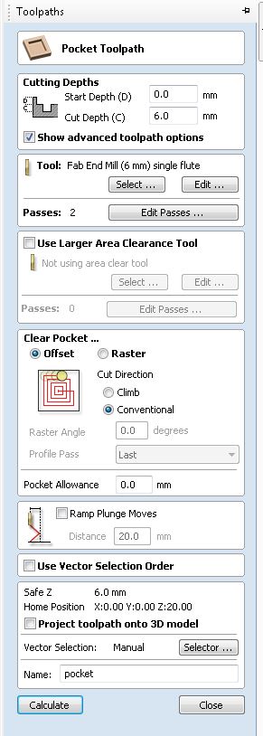
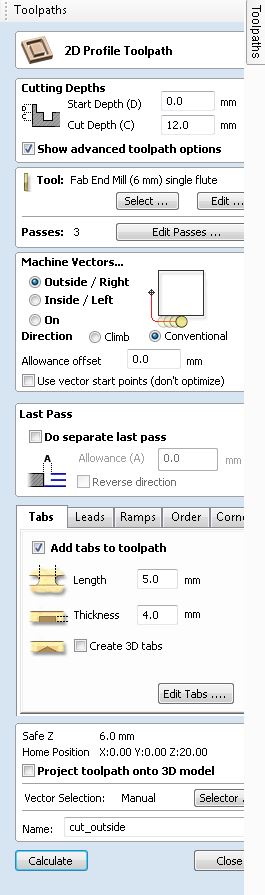
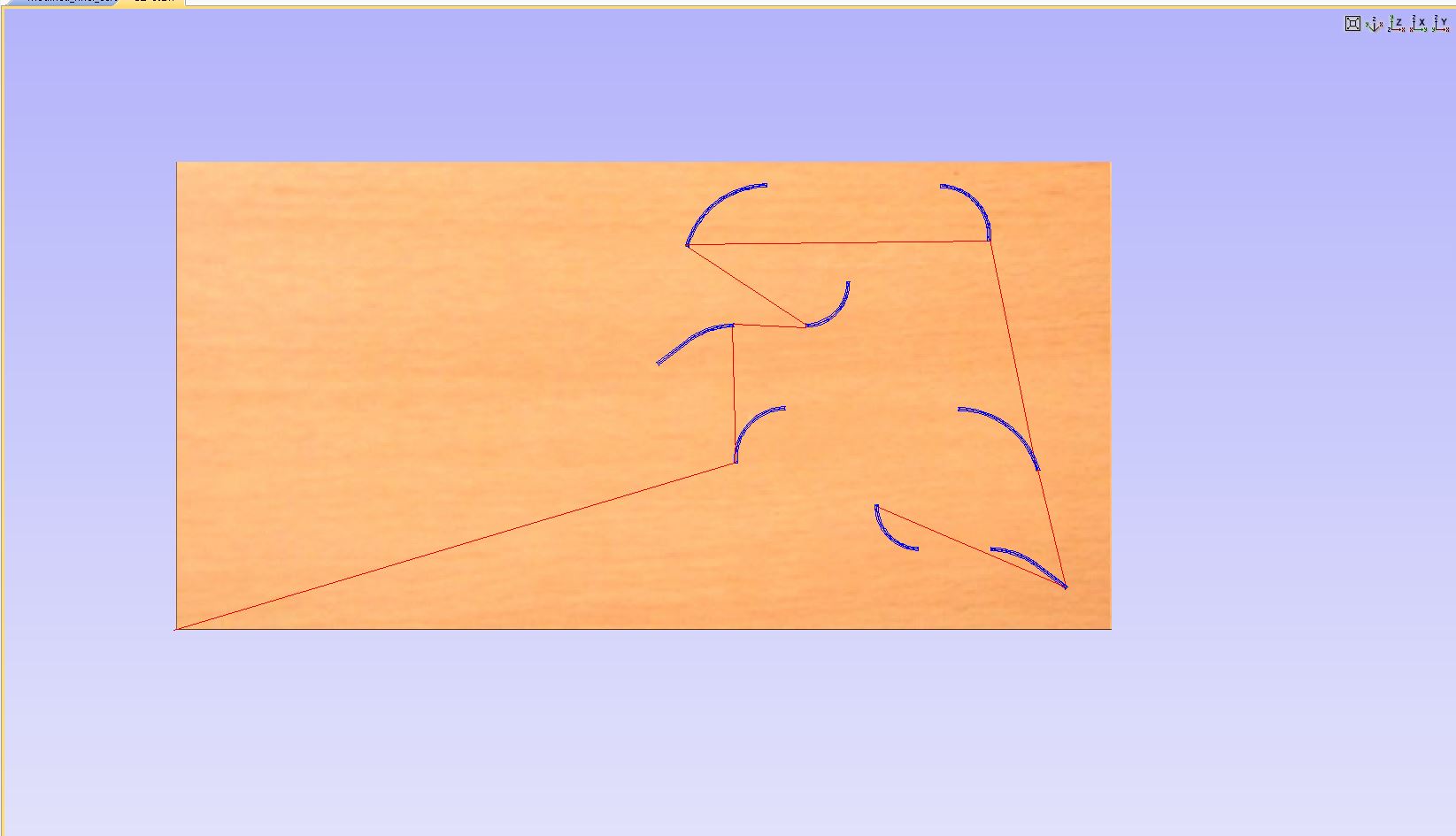
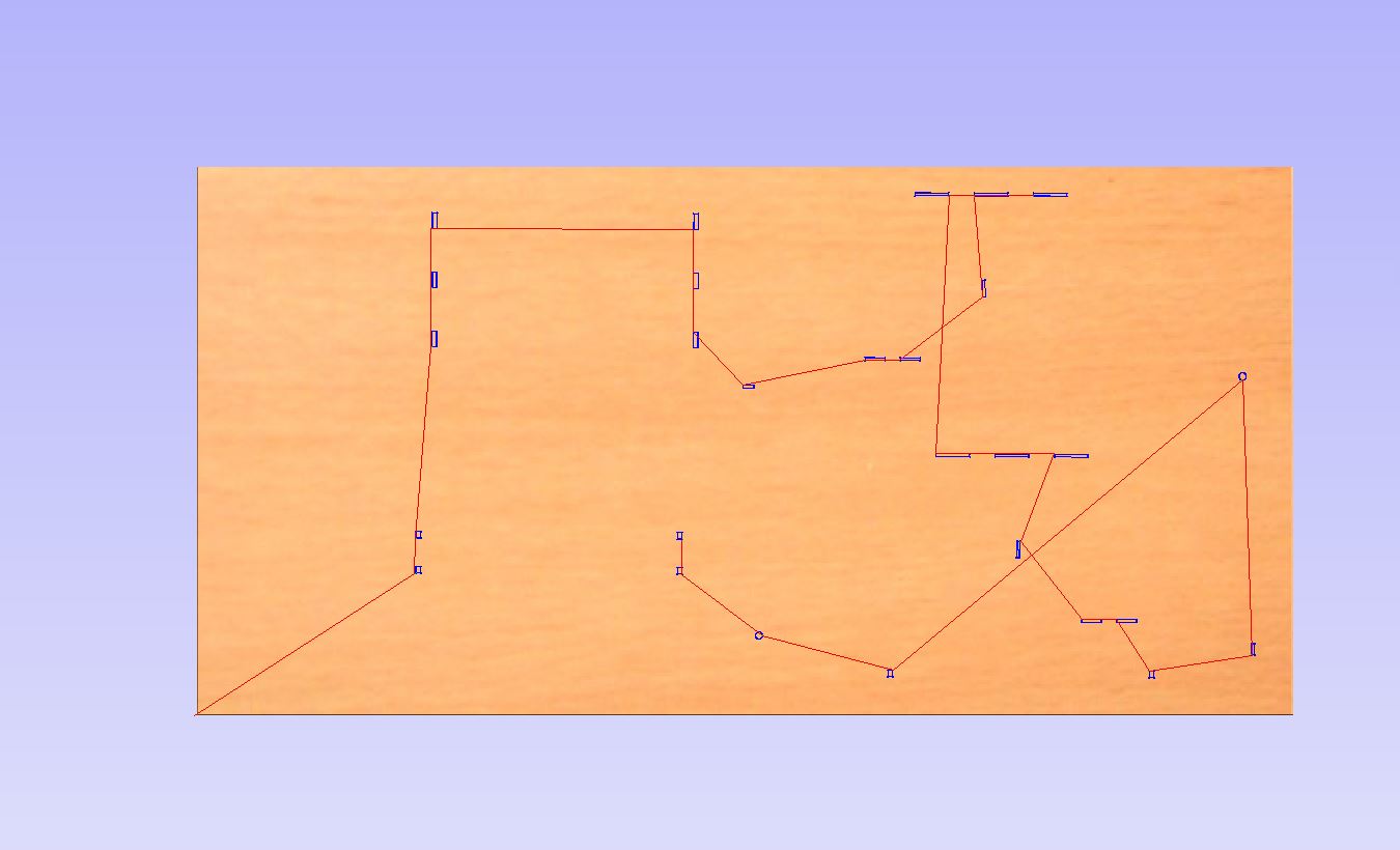
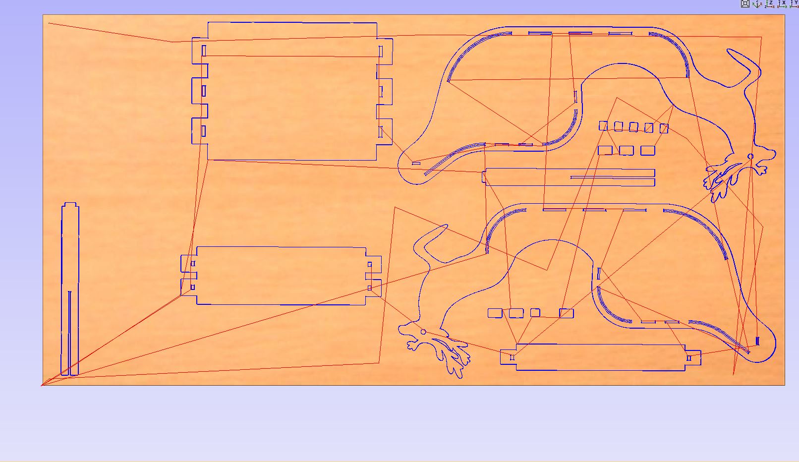
Here are the tool paths that I created:
 ....
....
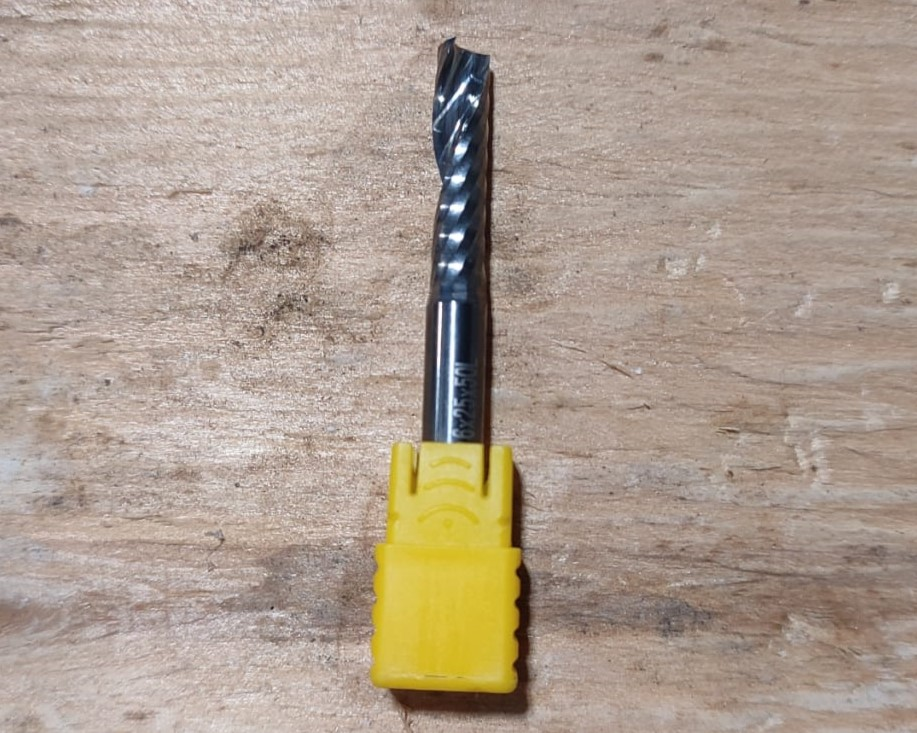
Mill Bit:
Single flute 6mm End Mill
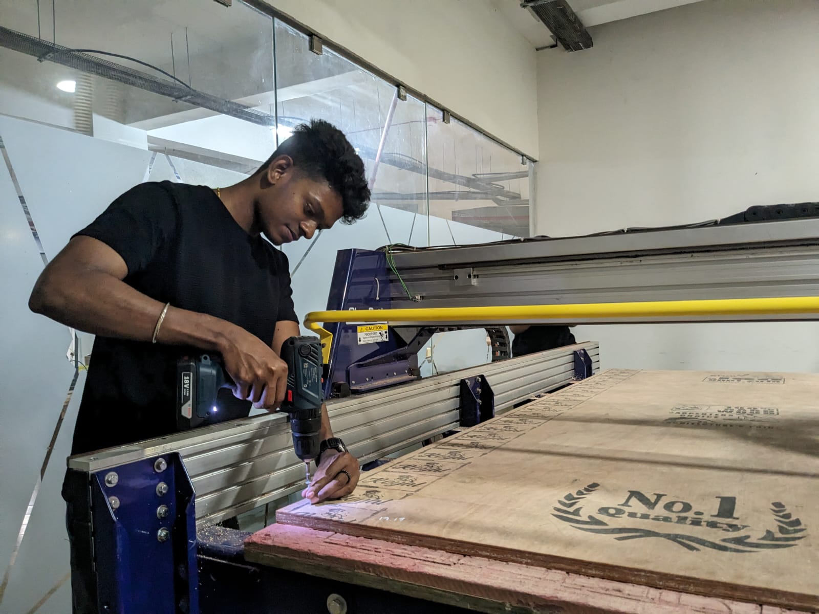
It is crucial to clamp the plywood securely before cutting to prevent any movement during the process. We use screws on the edges and in areas where the material will not be cut. Instead of calculating the positions manually, it's better to create a separate toolpath for the screw positions. Therefore, I provided the toolpath positions for pre-drilling where the screws will be placed.
I divided the milling process into four parts: Drill (Pre-drill), Pockets, Inner Cut, and Outer Cut.
ShopBot PRS Alpha 96 CNC Router
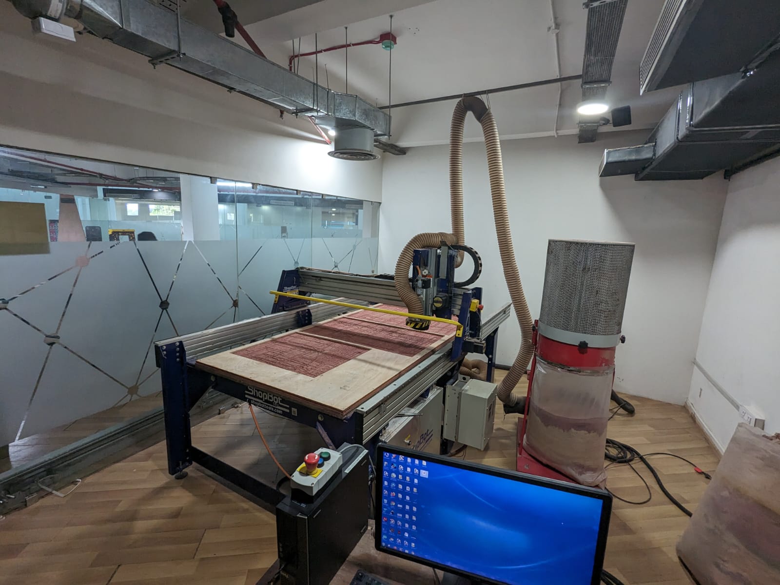
Features:
- Bed Size: 1.7526 x 2.438 m
- Table Thickness: 3/4" Plywood Bottom Layer & MDF Top Layer
- Stationary Bed
- Tool Module: Moves in X, Y, and Z directions
Once the toolpath files are ready, next step is to open ShopBot's software
ShopBot 3
.

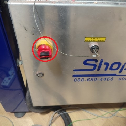
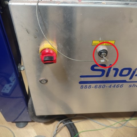
Switch on the ShopBot by turning the knob on its side panel.
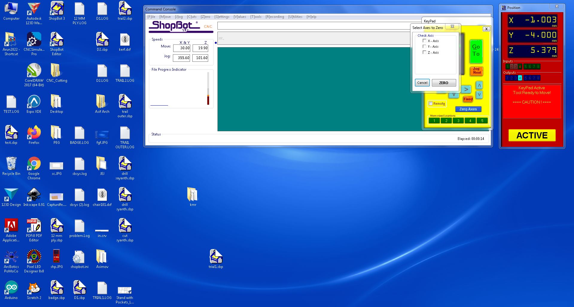
The next step is to set the origin.
Jog the module along the X and Y axes to set the zero position manually.
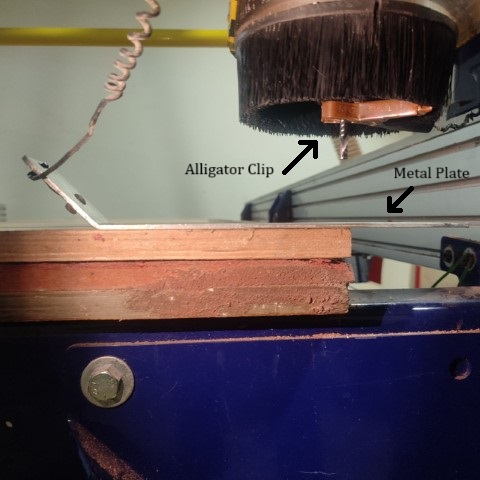
For the Z axis, use the metal plate and alligator clip provided with the machine. The machine will automatically detect the position when the clip contacts the plate and set the Z axis's zero position.
After moving the XYZ axes to their respective zero positions, reset the values of XYZ to zero.
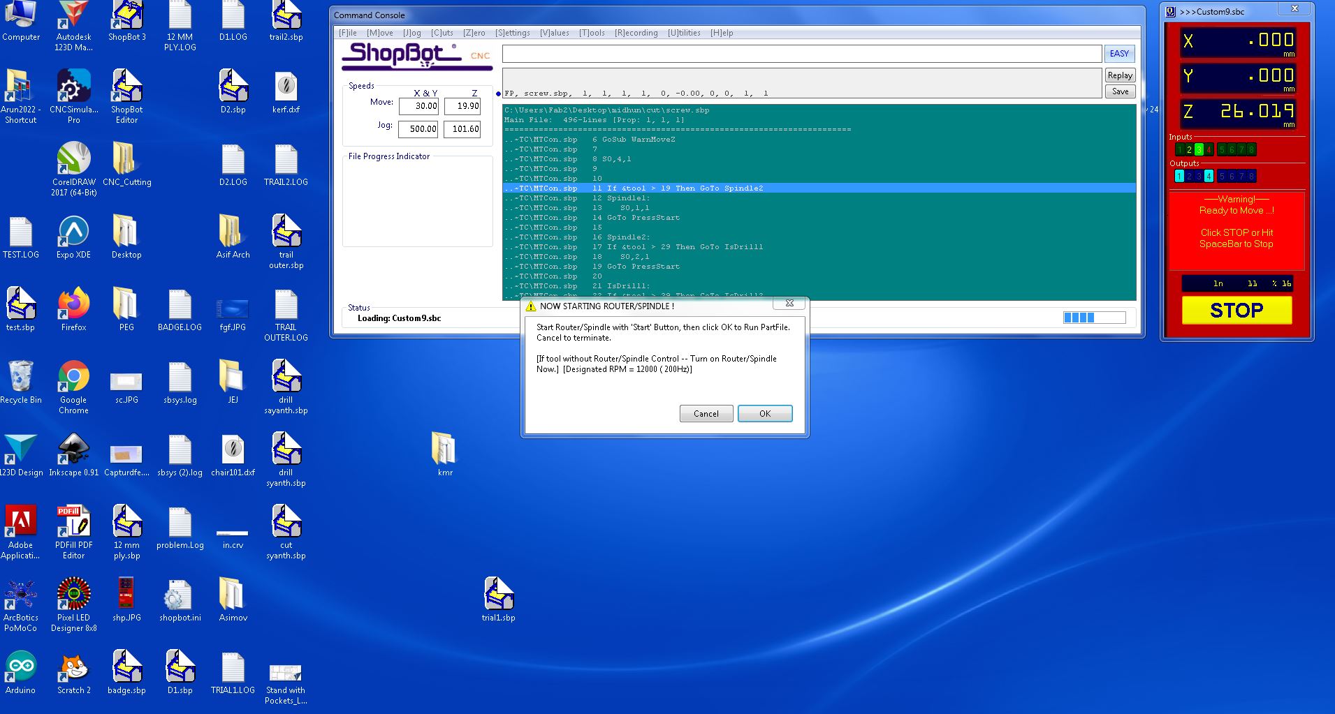
Once all three axes are zeroed, click on " Cut Part " to upload the file. Then, click on " Start ".
A pop-up box will appear requesting to switch on the spindle. To do so, turn the key provided at the side panel of the machine once.
Now, press the Start button on the remote. Once the spindle starts spinning, click OK on the dialogue box. Repeat this process for each of the four files you uploaded, and the design will be milled accordingly.
I utilized a mallet, hammer, and with the help of my friends and instructors i joined components together. Then, I used a sander to sand the sides for a smooth finish.
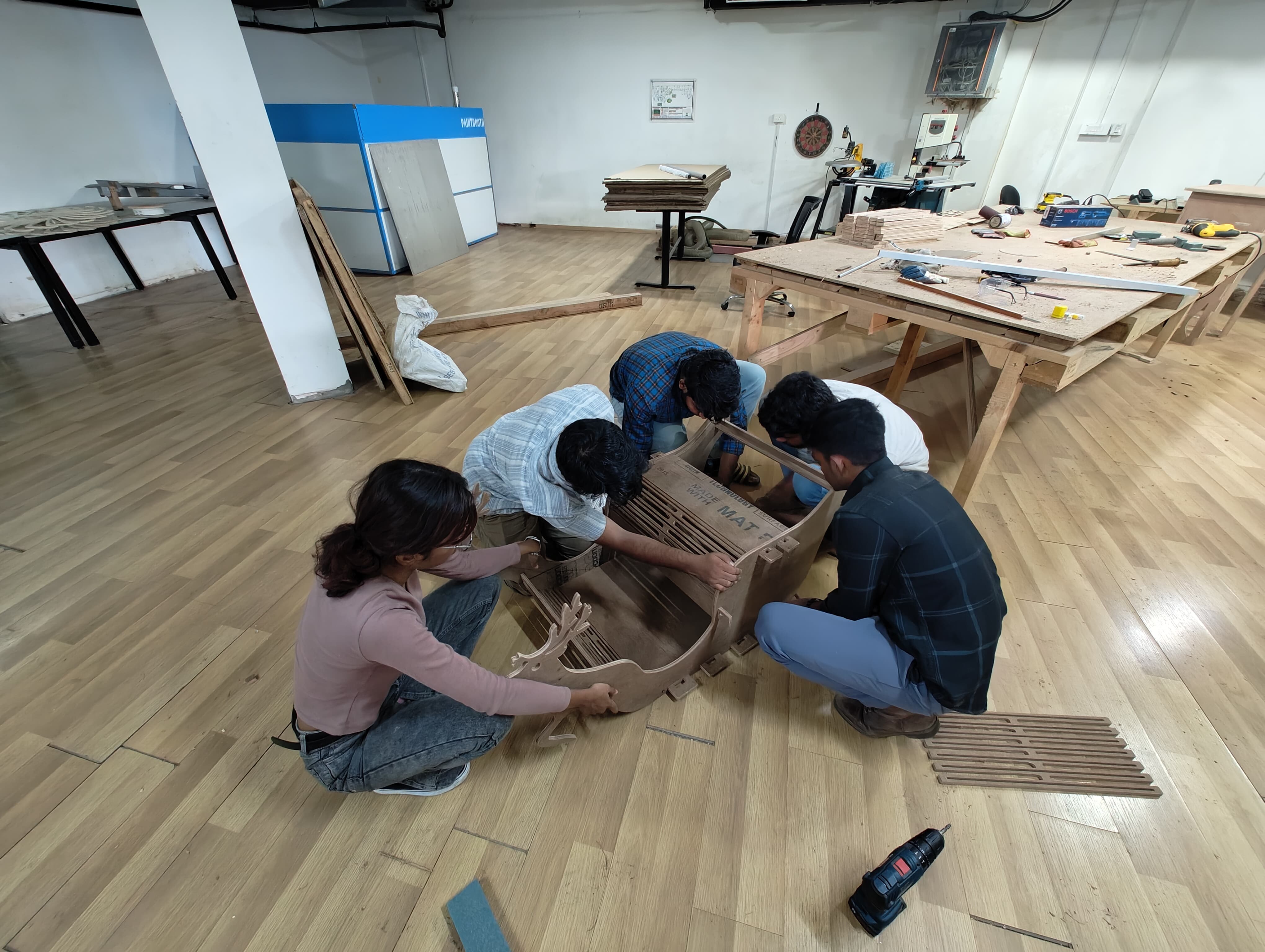


Additionally, I added four wheels to the bottom of the cart, making it possible to move around easily. Here are my friends playing with the cart that I made.